Recently, I had the opportunity to work on a project using an STM32 microcontroller and an Ethernet interface. Like others who have tackled this topic, I encountered a problem – the lack of “simple” guides. In most of the available sources, connecting the Ethernet interface and STM32 chips is described in a rather confusing way, and in my opinion, there is a lack of instructions describing how to configure this functionality in the simplest possible way, without unnecessary exploration of network aspects. That is why I decided to prepare this and related materials on the subject of Ethernet on STM32. In this article, I will show you the basic functionality of a UDP client. That is, code whose operation is, in a sense, the opposite of a UDP server. In the previous tutorial, the STM32 acted as a server to which the computer connected, this time we will create a server on the computer to which the microcontroller will connect.
In the projects I use the Nucleo F767ZI board, the codes are available for download on my GitHub profile.
Warning of new firmware version

When preparing the codes for this tutorial, I used CubeMX V6.12.1. If anyone wants to use the finished project that I provide on my GitHub profile, they will probably encounter a warning about the new firmware version. In that case, I recommend going ahead and using version 6.12.1.
Project configuration
When preparing a UDP client project, use the configuration described in the first article. It is identical and consists in selecting the RMII option for the Ethernet interface and the corresponding driver and IP address in the LWIP section.
Preparing the UDP Client library
udp_client.h
#ifndef INC_UDP_CLIENT_H_
#define INC_UDP_CLIENT_H_

void udpClient_connect(void);

#endif /* INC_UDPCLIENTRAW_H_ */
The structure of the udp_client.h header file is extremely simple and contains only a prototype of a function whose task is to connect to the server.
udp_client.c
#include "lwip/pbuf.h"
#include "lwip/udp.h"
#include "lwip/tcp.h"
#include "stdio.h"
#include "string.h"
#include "udp_client.h"
We start file C with the declaration of lwip libraries that support the Ethernet interface. In addition, it contains standard packages stdio.h, string.h, and the header file udp_client.h.
void udp_receive_callback(void *arg, struct udp_pcb *upcb, struct pbuf *p, const ip_addr_t *addr, u16_t port);
static void udpClient_send(const char *message);

struct udp_pcb *upcb;
char buffer[100];
In the next step, we declare prototypes of the function called after receiving data from the server – udp_receive_callback – and sending data via STM32 – udpClient_send.
Next, an udp_pcb structure is created for the UDP client and a buffer variable is created to store the received data.
void udpClient_connect(void)
{
    err_t err;

    /* 1. Create a new UDP control block  */
    upcb = udp_new();

    /* Bind the block to module's IP and port */
    ip_addr_t myIPaddr;
    IP_ADDR4(&myIPaddr, 192, 168, 8, 200);
    udp_bind(upcb, &myIPaddr, 1100);

    /* Configure destination IP address and port */
    ip_addr_t DestIPaddr;
    IP_ADDR4(&DestIPaddr, 192, 168, 8, 108);
    err = udp_connect(upcb, &DestIPaddr, 12);

    if (err == ERR_OK)
    {
        /* 2. Send "Hello World" message to server */
        udpClient_send("Hello World");

        /* 3. Set a receive callback for the upcb */
        udp_recv(upcb, udp_receive_callback, NULL);
    }
}
The udpClient_connect function connects to the server. In its first part, we create a new UDP block that we will work on, and then we configure the IP address and port of our microcontroller. In my case, it is 192.168.8.200 and 1100. Next, we need to specify the address and port of the server we want to connect to. It will be IP 192.168.8.108, port 12, i.e. the computer in my network.
If the connection is established correctly, a conditional function will be executed, sending the text “Hello World” to the server along with a return message.
static void udpClient_send(const char *message)
{
    struct pbuf *txBuf;
    int len = strlen(message);

    /* Allocate pbuf from pool */
    txBuf = pbuf_alloc(PBUF_TRANSPORT, len, PBUF_RAM);

    if (txBuf != NULL)
    {
        /* Copy data to pbuf */
        pbuf_take(txBuf, message, len);

        /* Send UDP data */
        udp_send(upcb, txBuf);

        /* Free pbuf */
        pbuf_free(txBuf);
    }
}
The structure of the function sending data is quite simple. First, we allocate a pbuf buffer that will contain the data to be sent. Then, if the previous operation was successful, we copy the data, send it, and release the buffer.
void udp_receive_callback(void *arg, struct udp_pcb *upcb, struct pbuf *p, const ip_addr_t *addr, u16_t port)
{
    /* Copy the data from the pbuf */
    strncpy(buffer, (char *)p->payload, p->len);
    buffer[p->len] = '\0';  // Ensure null termination

    /* Free receive pbuf */
    pbuf_free(p);
}
The last function is a callback that is automatically invoked after receiving data from the server. Its task is to assign the data to a buffer, while adding a NULL terminator at the end and releasing it after the operation is completed.
Main program code
/* Private user code ---------------------------------------------------------*/
/* USER CODE BEGIN 0 */
extern struct netif gnetif;
/* USER CODE END 0 */
In the main.c file, which contains the main program executed by STM32, we place a declaration of the netif structure named gnetif. This is a basic structure defined in the built-in LwIP (Lightweight IP) library that supports the network stack.
/* USER CODE BEGIN 2 */
  udpClient_connect();
  /* USER CODE END 2 */

  /* Infinite loop */
  /* USER CODE BEGIN WHILE */
  while (1)
  {
    /* USER CODE END WHILE */

    /* USER CODE BEGIN 3 */
	  ethernetif_input(&gnetif);
	  sys_check_timeouts();
  }
  /* USER CODE END 3 */
}
In the main while loop, we place the instructions ethernetif_input(&gnetif); and sys_check_timeouts();. Their task is to sequentially receive all data from the Ethernet port and assign it to the network stack, in other words, pass it to the gnetif structure, to which the pointer is placed in the argument. The second command checks and handles all timeouts related to the LwIP stack. Additionally, above the while loop there is a function that initializes the UDP client.
The program prepared in this way should be saved in the microcontroller’s memory, remembering to connect the Ethernet cable to the board beforehand. However, nothing bad will happen if you do this later.
Startup
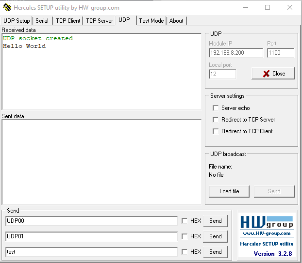
To check the code’s functionality, I used the Hercules program, available for free on the Internet. From there, specifically from the UDP tab, we can launch a server on our computer. The Module IP and Port tabs are insignificant; the most important one is Local port, i.e. the port on which the server will be created. Its IP address will match the computer’s IP address; the easiest way to check this value is with the arp -a command in the CMD console. After starting the server and connecting the power supply to the STM32, Hello World should appear in the received data after a while. This means that the microcontroller has successfully connected to the computer and sent the prepared data.
As you can see, implementing a UDP client in STM32 is quite simple. In the next tutorials, we will take a closer look at a slightly more sophisticated communication protocol, namely TCP.