Practically every day we encounter bar codes of various kinds. Although we don’t usually pay attention to them, they play a very important role in today’s world – the identification of products in the store, the flow of packages in logistics centers or the proper distribution of components in production processes. Barcodes are used in each of these areas, thanks in part to their simplicity. The small size of the code can be easily scanned by an automatic scanner or an operator equipped with the appropriate equipment.
There are many off-the-shelf scanning devices on the market, but there are also small modules that we can easily integrate into the equipment being designed. It is one such design that we will take a slightly closer look at today.
What are barcodes?

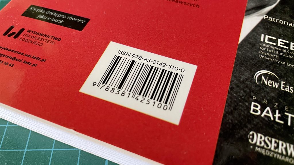
However, before we move on to scanners, let’s answer the question of what a barcode basically is. Simply put, it is a graphic representation of certain information written as a sequence of light and dark lines. The size, width or general appearance of the code is defined by rigid standards. It is also worth knowing that nowadays we can most often meet with linear one-dimensional codes (such as in the picture) and two-dimensional QR codes.
In a bar code, each digit consists of seven identical blocks, in black or white. The width of each bar depends on what character you want to write. It is accepted that each digit is represented by two white and two black bars, always arranged in the same way – white – black – white – black.

It is slightly different in QR codes. With these two-dimensional codes, numeric and alphanumeric information is written in the form of black and white squares representing the corresponding binary values. In addition, each QR code also contains three slightly larger squares, which are position markers. Thanks to them, you know where the beginning of the stored information is located.
How does a barcode scanner work?

Let’s stop for a moment at the scanning process itself and answer the question of how such a scanner works. Any scanning device is really based on two components a laser diode or high-brightness LED and a photodetector. The laser diode or LED emits a beam of light that hits a scattering lens. When in the path of the scattered light, there is a barcode then the light will be reflected, but only by the white parts of the code, the dark lines will absorb all the light. It can be said that each scanner actually reacts to the empty spaces between the black bars of the barcode. The light beam reflected and shredded by the barcode goes further to the photodetector. Its task is to recognize where the black bars have been placed in the barcode and, based on this, generate electrical signals that are later processed by the rest of the scanner’s electronics. When scanning QR codes, the situation is identical except that the light is reflected by the white squares, not the dashes.
Sometimes the scanner can be equipped with a third element, which is an additional white light-emitting LED. Its task is to illuminate the scanned code, so that the possible reading error is minimized as much as possible.
GM65 scanner

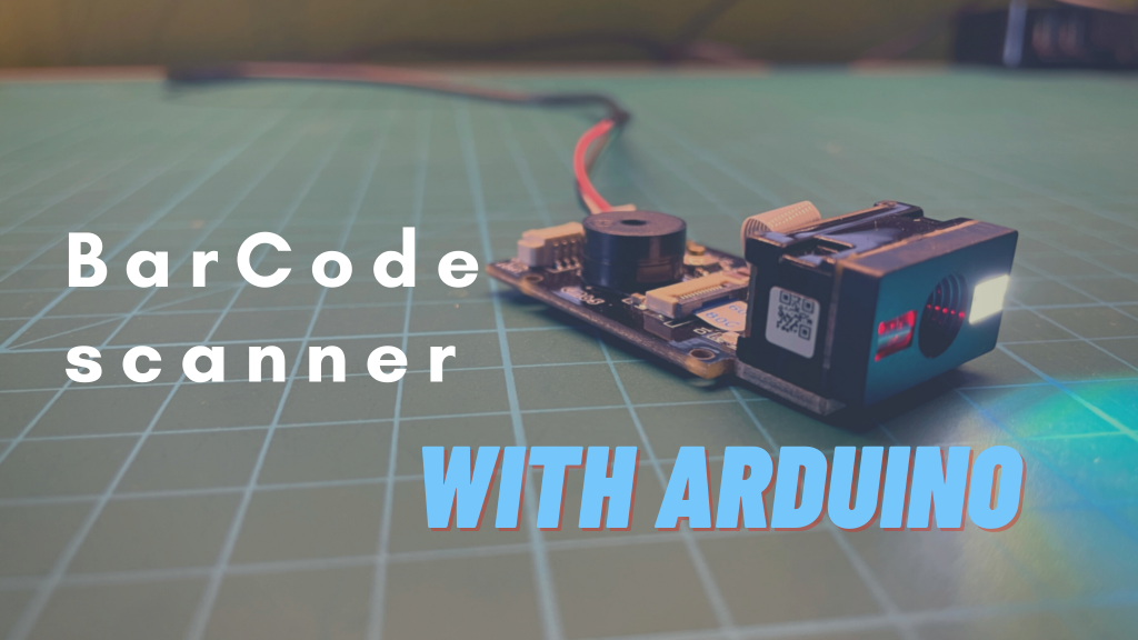
The device that will allow us to scan some barcodes today will be a scanning module with the designation GM65. This is a small device, capable of scanning barcodes as well as two-dimensional QR codes. Below you can see some of the most important technical parameters of this equipment.
- Power supply voltage: 5 V DC
- Rated current: 160 mA
- Scanning angle: 34° (horizontal), 26° (vertical)
- Minimum contrast ratio: 30%
- Interfaces: UART and USB
- Supported one-dimensional code standards: Code 11, Code 39/Code 93, UPC/EAN, Code 128/EAN128, Interleaved 2 of 5, Matrix 2 of 5, MSI Code, Industrial 2 of 5, GS1 Databar(RSS)
- Supported two-dimensional code standards: QR, Data Matrix, PDF417
- Operating temperature range: 0°C to 50°C
- Dimensions 46.8mm x 27.5mm x 11.8mm
The GM65 is powered by 5V and supports two communication standards. The easiest way is to connect the device with a dedicated USB cable, in which case it is treated like a keyboard. However, if you want to integrate the device with, for example, a microcontroller, it is easier to use the built-in UART interface, with which the scanner sends a barcode processed into a string of characters.
It is also worth mentioning that the module is equipped with a buzzer and a single button to turn the device on and off.
Scanner configuration
In order for the scanner to work properly, it must be properly configured. This process is accomplished by scanning the appropriate QR code, I have included the most important codes below, but you can find many more in the documentation. If you will be scanning the codes directly from the computer screen, I recommend covering the white LED, as the scanner does not always catch the codes when it illuminates the LCD matrix. When the configuration code is scanned correctly, the blue LED on the module will light up.

The first three codes allow you to choose how to communicate with the scanner, and to reset it to factory settings.

With another set of codes, we can modify the interval time between scans.

The codes above allow control of the white, illuminating LED.

The following codes are used to control the buzzer.
GM65 and Arduino

In addition to connecting the scanner directly to the computer’s USB port, we can connect it to any microcontroller or processor equipped with a UART interface. To show you what such communication looks like I will run some simple code that will receive data from the GM65 and send it to the computer’s serial port.
I decided to connect the scanner to the Teensy 3.5 board (link) really for two reasons. The main one is that the board has several UART interfaces, so you can easily connect it to the computer and the GM65 module. In the case of the Arduino UNO, for example, this is not so easy, because the ATmega328 installed there has only one UART, shared with the USB interface. In such a case, without the so-called software serial you can not do without. Besides, the Teensa board has been out of commission for quite a long time, which was another argument to just connect the scanner to it.
Physically connecting the module is nothing difficult, we just need to connect the power supply, and connect the Tx, Rx ports of the module to the Rx and Tx of the microcontroller.
#include <Arduino.h>  //Library included in VSC

void setup()
{
  Serial.begin(9600);  //communication with the computer
  Serial1.begin(9600); //communication with GM65 module
}

void loop()
{
  if (Serial1.available()) //Checking if any data has been received
  {
    while (Serial1.available()) //Read bit by bit until UART buffer is empty
    {
      char input = Serial1.read(); //Writing the received data to the input variable
      Serial.print(input); //Display input variable
      delay(5);
    }
    Serial.println(); //Move to a new line
  }

}
Operation of the scanner is quite simple and is based on the basic functionality of the UART interface. At the beginning, of course, we need to define two serial ports, one for communication with the computer, the other with the scanning module. In the main loop of the program we check if the serial port has received any data, if so a while loop is started, which assigns to the input variable the received data, while sending it to the second serial port. After the whole operation thanks to the Serial.println(); command, the cursor on the computer’s serial port goes to a new line.

After launching the project, you can see the code scanned by the reader in the form of a string of characters. You have to admit that it is really easy to run this type of scanner, and in combination with the right system it really gives a lot of possibilities. For example, you can quite easily build a simple warehouse system, for electronic parts connected to a database. The possibilities are many, because barcodes are a very versatile way of encoding information.
Sources:
- https://how2electronics.com/barcode-qr-code-reader-using-arduino-qr-scanner-module/
- https://www.dfrobot.com/product-1996.html
- https://www.pjrc.com/store/teensy35.html
- https://www.posnet.com.pl/rodzaje-i-budowa-kodow-kreskowych
- https://en.wikipedia.org/wiki/Barcode
- https://www.posnet.com.pl/jak-dziala-skaner-kodow-kreskowych
- https://raw.githubusercontent.com/DFRobot/DFResources/master/Others/DFR0660%20Datesheet.pdf
