
graphical interface. LEDs, displays, screens… there are really many ways to graphically show the progress of the program or task being performed. However, in order to display all the information correctly, you need to properly handle the chosen display. In this article you will learn how to run a 7-segment display on an FPGA chip.
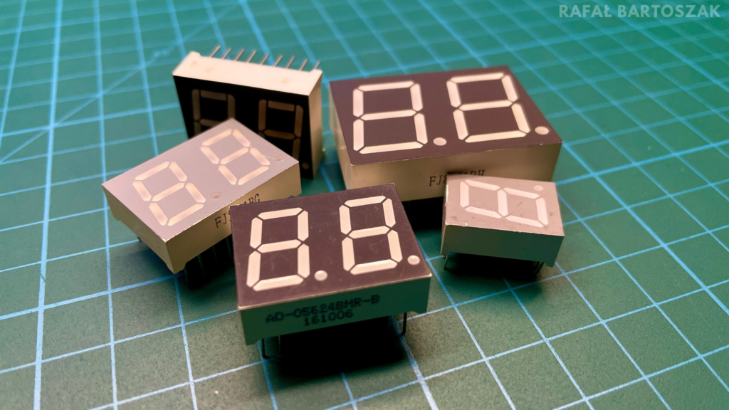
The concept of the 7-segment display is ingenious in its simplicity. A number of LEDs arranged in such a way that lighting the appropriate segments shows a known number or character. We can distinguish two types of displays:
- Display with common anode – common (+) for all segments,
- Display with a common cathode – common (-) for all segments.
We can handle the 7-segment display in two ways. In the first, each segment is handled by a separate pin of the FPGA chip or microcontroller. If we use only one display this way, will be ideal, but if the number of displays increases, there may be a problem in the lack of free chip outputs. To solve this problem, a way of handling displays was created, in which all pins are connected to each other. The signal of the sign to be displayed goes to all displays at the same time, but only one display is running at a time. This happens so fast that the human eye is not able to catch changes in the displayed characters, so it seems to us that the digits are displayed continuously. This way of operating a display is called multiplexing.

Mimas v2 schematic fragment (https://numato.com/docs/mimas-v2-spartan-6-fpga-development-board-with-ddr-sdram/)
The Mimas v2 board, on which this article is based, has a built-in three-character 7-segment display, so today we will look at the second way to handle this type of design. The code described below, in addition to handling the displays themselves, also implements the function of incrementing the displayed number by one every second.
library IEEE;
use IEEE.STD_LOGIC_1164.ALL;
use IEEE.std_logic_unsigned.all;

entity main is
    Port(
		clock_100Mhz : in STD_LOGIC;		                --clock
      reset : in STD_LOGIC; 				                --reset
      Anode_Activate : out STD_LOGIC_VECTOR (2 downto 0);   --display activation
      LED_out : out STD_LOGIC_VECTOR (6 downto 0)	        --data bus
	  );
end main;
At the very beginning, we need to declare the appropriate libraries and describe the project’s external ports. These will include a clock input for the 100MHz signal, a reset input connected to the SW3 button that is located on the board, a 3-bit output to activate the individual displays, and a 7-bit data output for the displays.
architecture Behavioral of main is

signal one_second_counter: STD_LOGIC_VECTOR (27 downto 0);  --1s counter
signal one_second_enable: std_logic;			            --number +1
signal displayed_number: STD_LOGIC_VECTOR (11 downto 0);    --number displayed
signal LED_BCD: STD_LOGIC_VECTOR (3 downto 0);		        --bcd variable
signal refresh_counter: STD_LOGIC_VECTOR (19 downto 0);	    --refresh counter
signal LED_activating_counter: std_logic_vector(1 downto 0);--counter activating a single display

begin
The next part of the code declares all the internal signals used in the project, their meaning is explained in the comments.
process(LED_BCD)						--decoder bcd-7segment
  begin
    case LED_BCD is
    when "0000" => LED_out <= "0000001"; -- 0
    when "0001" => LED_out <= "1001111"; -- 1
    when "0010" => LED_out <= "0010010"; -- 2
    when "0011" => LED_out <= "0000110"; -- 3
    when "0100" => LED_out <= "1001100"; -- 4
    when "0101" => LED_out <= "0100100"; -- 5
    when "0110" => LED_out <= "0100000"; -- 6
    when "0111" => LED_out <= "0001111"; -- 7
    when "1000" => LED_out <= "0000000"; -- 8
    when "1001" => LED_out <= "0000100"; -- 9
    when "1010" => LED_out <= "0000010"; -- A
    when "1011" => LED_out <= "1100000"; -- B
    when "1100" => LED_out <= "0110001"; -- C
    when "1101" => LED_out <= "1000010"; -- D
    when "1110" => LED_out <= "0110000"; -- E
    when others => LED_out <= "0111000"; -- F
    end case;
end process;
In the first synchronous process block, a function was implemented that decodes the LCD_BCD signal into a 7-segment code assigned to the LED_out output. The code is based on the case function and allows displaying all available characters from 0 to F.
process(clock_100Mhz,reset)					--refresh counter 10.5ms
	begin
    if(reset='0') then
        refresh_counter <= (others => '0');
    elsif(rising_edge(clock_100Mhz)) then
        refresh_counter <= refresh_counter + 1;
    end if;
end process;

LED_activating_counter <= refresh_counter(19 downto 18);
Next, a counter is described that will refresh the displays every 10.5ms or so. This is a 20-bit counter, whose value is increased by one with each clock beat. From our perspective, a refresh rate of 100MHz is too high, so we use the 19th and 18th bits of the counter, which are assigned to the LED_activating_counter signal.
process(LED_activating_counter)							--mux for display
  begin
    case LED_activating_counter is
    when "00" =>
        Anode_Activate <= "011";
        LED_BCD <= displayed_number(11 downto 8);
    when "01" =>
        Anode_Activate <= "101";
        LED_BCD <= displayed_number(7 downto 4);
    when "10" =>
        Anode_Activate <= "110";
        LED_BCD <= displayed_number(3 downto 0);
    when others =>
        Anode_Activate <= "111";
        LED_BCD <= displayed_number(3 downto 0);
    end case;
end process;
In the next part of the code, a multiplexer based on the case function is described. With it, the generated digit will show on the corresponding display. Based on the LED_activating_counter variable, corresponding signals are assigned to the Anode_activate and LCD_BCD signals.
process(clock_100Mhz, reset)					--1s counter
	begin
        if(reset='0') then
            one_second_counter <= (others => '0');
        elsif(rising_edge(clock_100Mhz)) then
            if(one_second_counter>=x"5F5E0FF") then
                one_second_counter <= (others => '0');
            else
                one_second_counter <= one_second_counter + "0000001";
            end if;
        end if;
end process;

one_second_enable <= '1' when one_second_counter=x"5F5E0FF" else '0';
Next is placed a counter whose task is to generate a ‘1′ state for the one_second_enable signal every one second. This is a 28-bit counter, which is reset when the state x “5F5E0FF” is reached. This is the number that, when clocked at 100MHz, will appear at the counter’s output after about a second.
process(clock_100Mhz, reset)						--counter of the displayed number
	begin
        if(reset='0') then
            displayed_number <= (others => '0');
        elsif(rising_edge(clock_100Mhz)) then
             if(one_second_enable='1') then
                displayed_number <= displayed_number + x"001";
             end if;
        end if;
end process;

end Behavioral;
In the last part of the code another counter is placed, which generates the displayed number. It is in the form of a 12-bit BCD code, whose value is incremented by one every one second based on the one_second_enable signal.
I implemented the project on the Spartan 6 chip, you can see the operation in the video above.
Sources:
- https://numato.com/docs/mimas-v2-spartan-6-fpga-development-board-with-ddr-sdram/