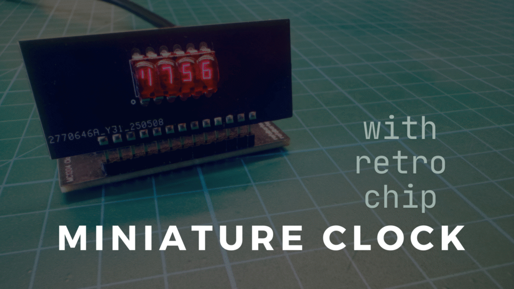
Rumor has it that the only silicon structures that Polish engineers interfered with were clock circuits. It is difficult to confirm this, however, as it is known that factories in communist Poland produced silicon from ready-made designs, but not much is known about our native designs. At that time, technologies of this type were quite well protected, but who knows, there is a grain of truth in every rumor. Miniature clock with a retro integrated circuit
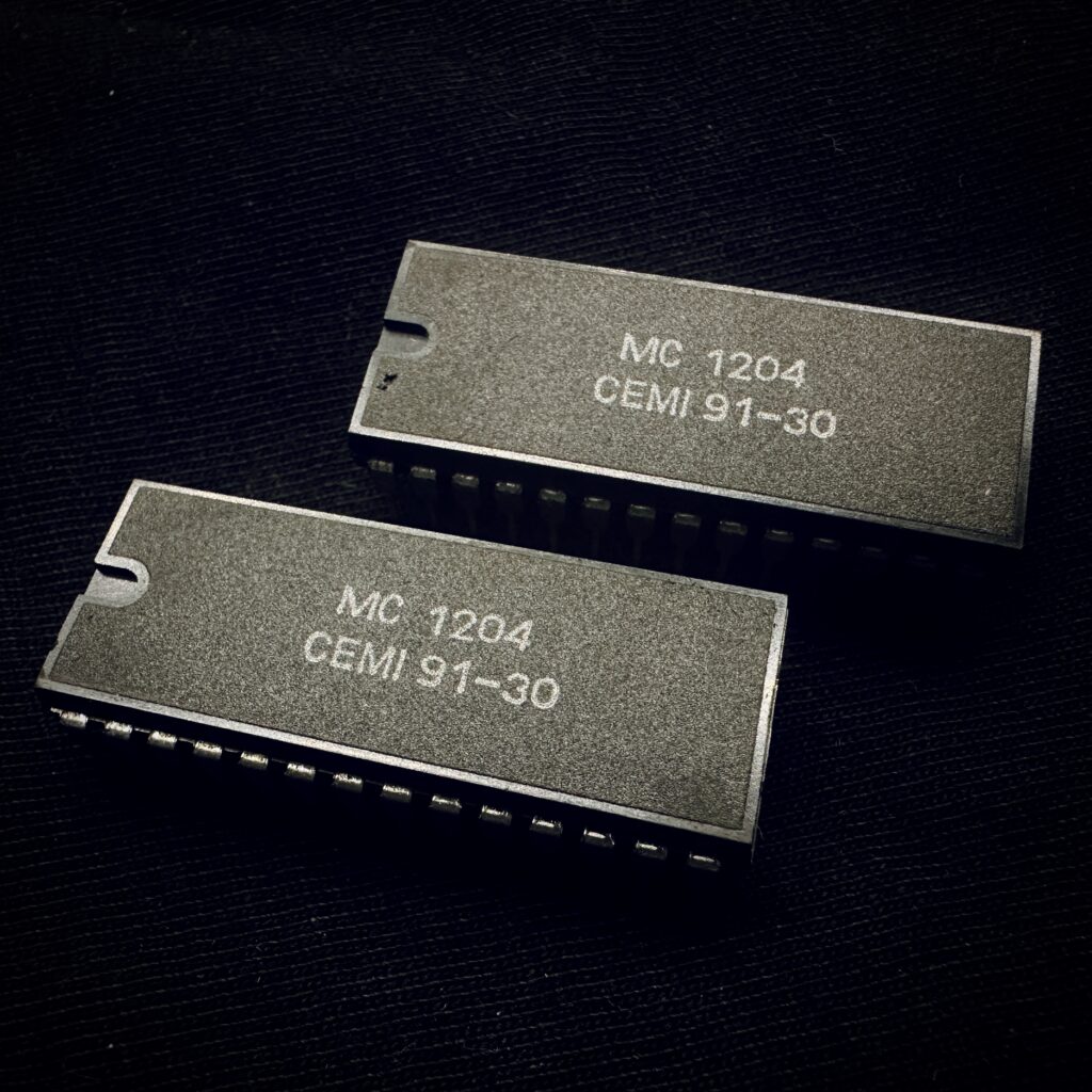
MC1204 chips, this photo comes from my Instagram profile, which I encourage you to visit.
The family of clock circuits manufactured by Warsaw-based CEMI is not that small. It includes smaller and larger chips with various functionalities, compatible with specific types of displays. In this article, however, I would like to focus on one specific model, or rather two – the MC1204, which I acquired some time ago.
These circuits, manufactured in week 30 of 1991, are four-function clocks that work with LED displays. They allow you to read hours and minutes, seconds, and the day and month. The system can operate in 12-hour or 24-hour mode and, according to information available online, is characterized by low energy consumption.
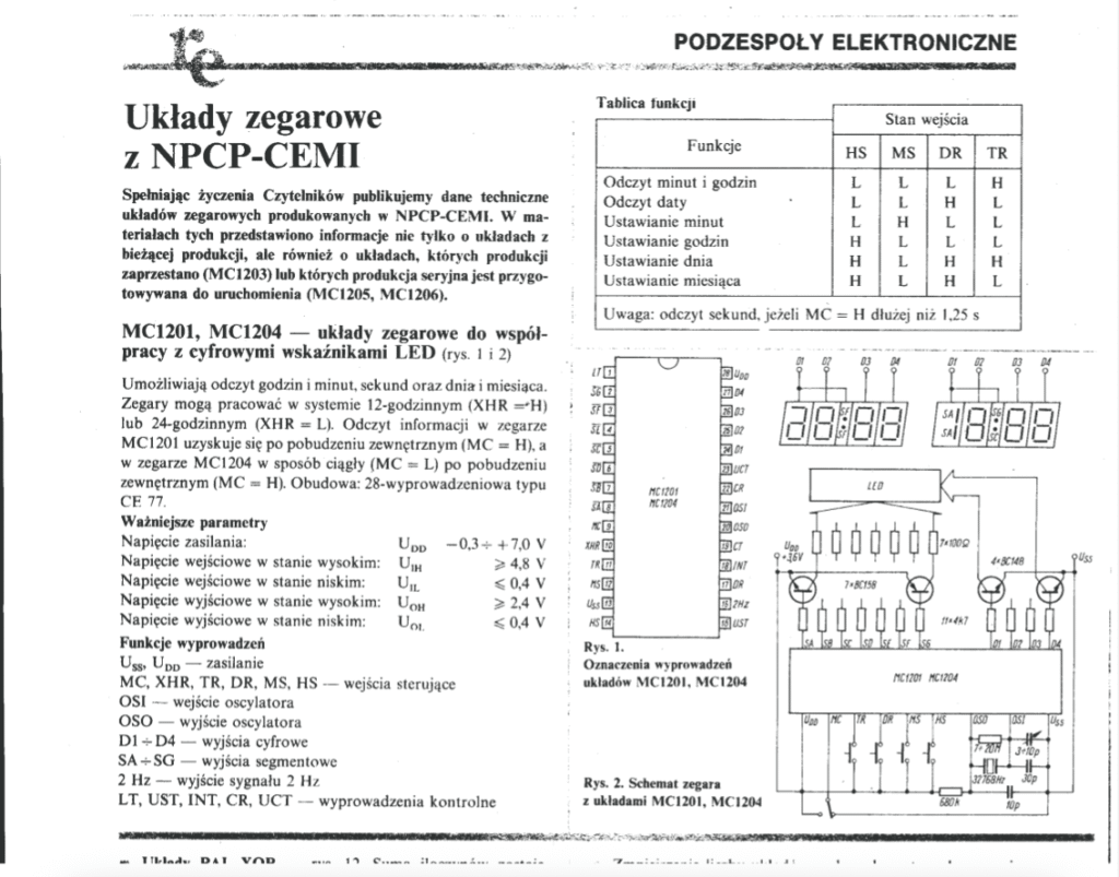
Basically, the MC1204 can be described as a complete clock system that requires few additional components to operate. From the design documentation, we learn that the chip requires an external clock circuit based on a quartz resonator and several buttons that allow you to set the time and date and trigger the supported functions. Additional transistors are also useful for controlling the display, both for individual segments and for outputs common to specific digits. As can be easily seen, the signals for the LED indicator are multiplexed.
With two MC1204 units and some documentation at my disposal, I decided to check whether they functioned correctly and to partially recreate the diagram shown above.
First start-up
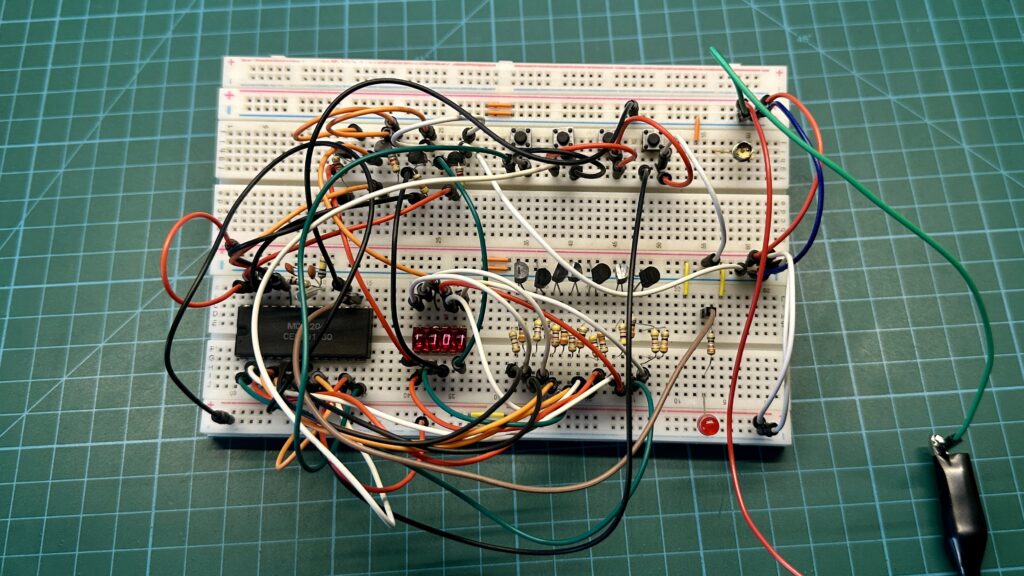
The first thing I tested was, of course, the contact board. The circuit prepared on it confirmed that both chips were working correctly, and the time displayed even after a few days matched the reference, which was my main concern. I suspected that after some time, the MC1204 readings might drift. To work with the chip, I chose a miniature four-digit display from HP, model number 5082-7414. BC557 transistors were responsible for controlling individual segments, while the anodes were controlled by BC337. In addition, the board features buttons for setting the time and date and for calling up the seconds display function. You can also see a red LED connected to the output of the circuit described as a 2Hz signal output. This can be used as a control pin or to control the indicators between the digits on the display.
Knowing that the circuits from the defunct CEMI factory were still functional, I came up with the idea of giving them a second life and designing a miniature clock. I also decided to use an HP display for this purpose. The aim of the project was to create the smallest possible PCB, not much larger than the chip itself, which meant that all accompanying components had to be as small as possible. The display itself was to be placed on a separate laminate, which would be connected perpendicularly to the main module. In terms of functionality, I assumed that the clock would only display the current time, with the option of displaying seconds via a button. I deliberately decided not to include the date or additional flashing segments between the digits, as I personally dislike this solution. The whole thing was to be powered via a USB connector.
Clock design
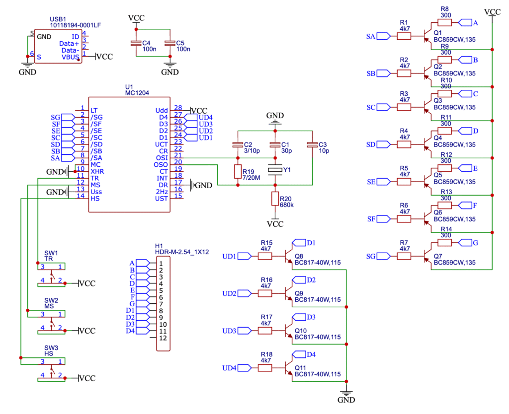
Based on the prepared prototype and a fragment of the documentation, I prepared a circuit that was later used to design the PCB boards. The whole thing is powered by a microUSB connector, and capacitors C4 and C5 are responsible for voltage filtering. Three buttons are connected to the main integrated circuit, two of which allow you to set the current hour and minute values, while the third displays the seconds. The clock circuit consists of a 32.768 kHz quartz resonator and several passive components. Originally, capacitor C2 was supposed to be an adjustable trimmer, but I decided to use a regular type of this component. It has a value of 6 pF, while resistor R19 has a resistance of 10 MΩ. In the diagram, I decided to include the value ranges of these components in accordance with the original documentation. The display is controlled by BC859 transistors controlling individual segments and BC817 transistors connecting the anodes of specific digits to ground. I decided to change the type of transistors from the prototype because I had the SMD version in my stock. The display itself was placed on a separate board connected to this circuit with an H1 goldpin connector.
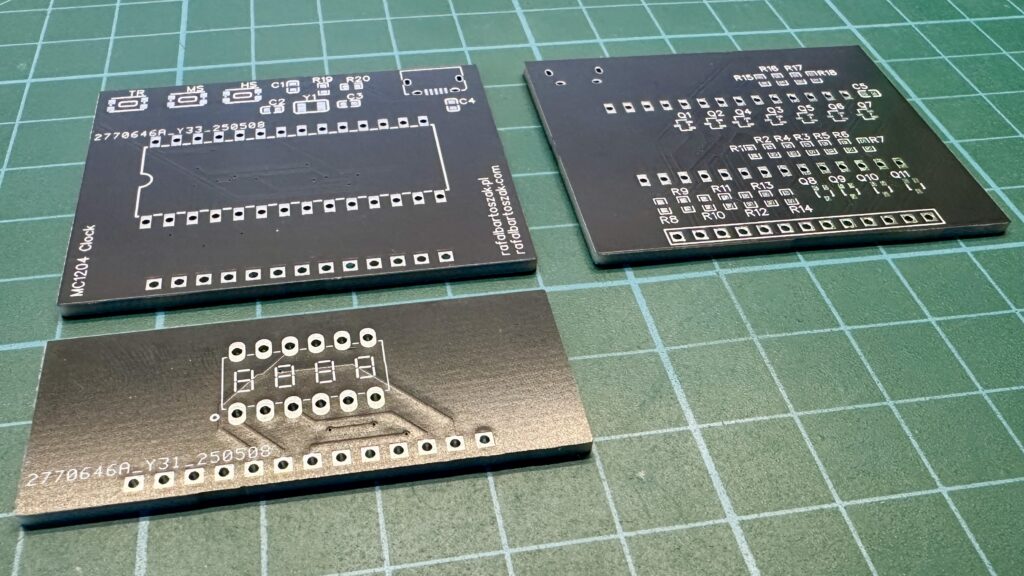
Based on the diagram, I designed two PCBs, one of which houses the MC1204 along with all accompanying components, while the other is used only to mount the display. As you can see, the largest component is the chip itself, in line with the assumption that the design should be fairly small. The other passive components are 0603 size, and the transistors in SOT323 packages are located on the other side of the laminate.
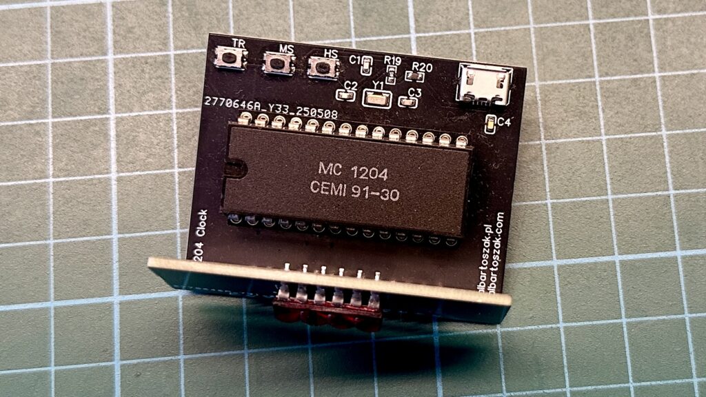
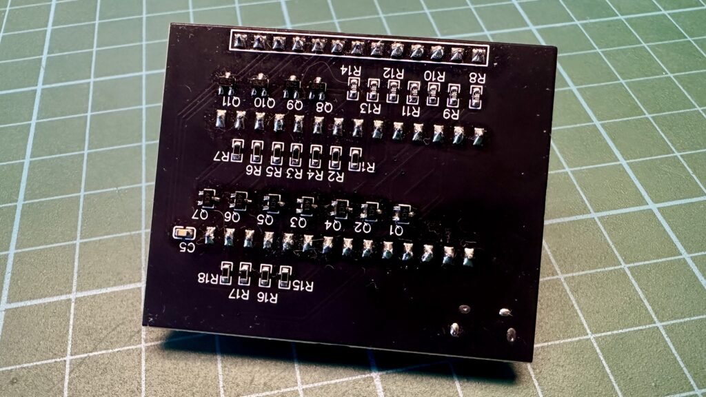
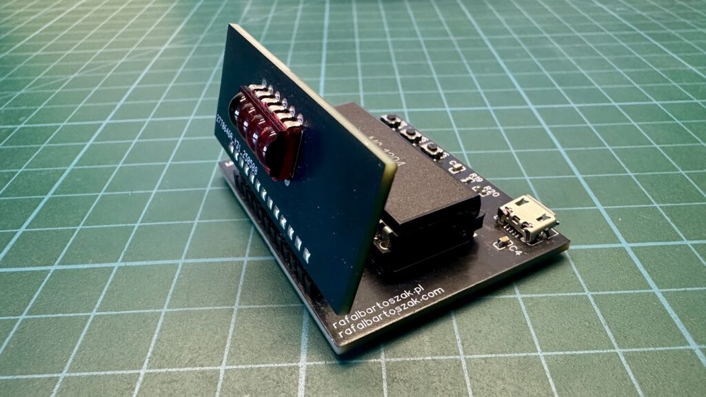
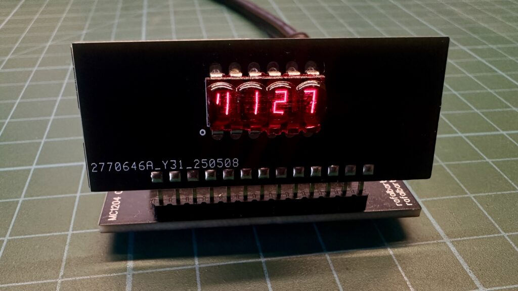
After connecting the power supply, the clock will display the time set using the MS and HS buttons. It is displayed as four digits with the first digit segment active at all times.
Additionally, pressing the TR button activates the seconds display, as you can see in the video above.
In this way, two retro components – the MC1204 and the HP display – have been given a new lease of life in the form of a miniature clock, which I have placed below the main monitor on which it works. Full schematics and Gerber files for the PCB boards can be found on my GitHub profile.
