Any electronic equipment must be powered in some way, without the right voltage it will not work at all or will work, but only for a fraction of a second. There are quite a few solutions and designs whose task is to bring energy to the designed circuit. Some of the most commonly used are linear stabilizers and voltage converters. We will leave stabilizers for another material, while today I would like to tell you a little about the operation and design of inverters. In addition, we will also look at their problems and try to solve them.
Also see:
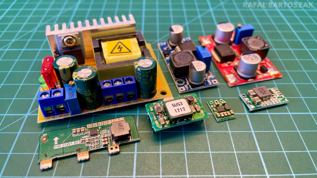
Usually voltage converters take the form of electronic modules, on separate PCBs. This is quite a practical solution, the finished module can be easily attached to a pre-designed circuit or can be used to power a prototype circuit built on a contact board. We can also meet with inverters on the occasion of larger printed circuits. Equipment manufacturers more than once decide to use these designs to power individual components of a larger system.
Regardless of what form the voltage converter will take, its task is really one – to convert voltage, the main division of inverters also follows from this:
- Step-down (buck) inverter – lowering the voltage,
- step-up (boost) inverter – increasing the voltage,
- step-up/down converter (SEPIC) – such a module can both increase and decrease the input voltage.
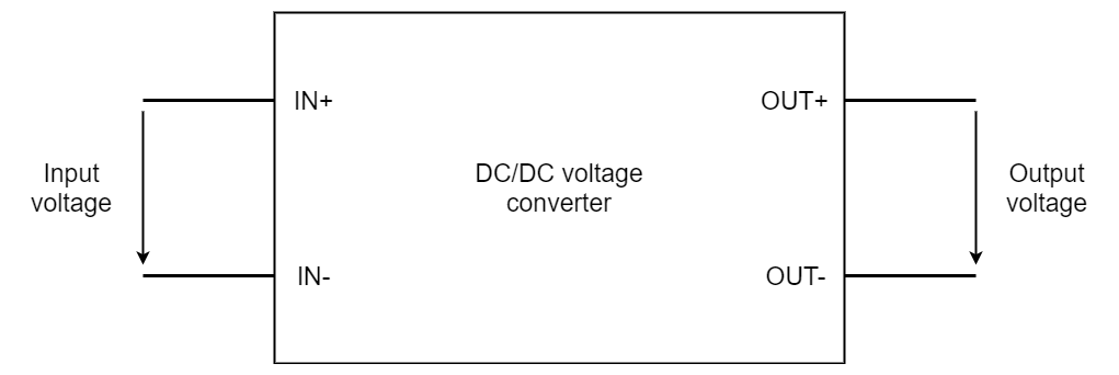
The concept of DC/DC voltage converters is best considered as an ordinary quadruple with input and output on opposite sides. Each inverter needs its own supply voltage, based on which the output voltage will be generated. It can be higher or lower relative to the potential at the input, depending on the specific type of inverter. A fairly common procedure used by manufacturers is the ability to adjust the output voltage through a potentiometer or a jumper placed directly on the laminate. Voltage converters come in different variations, usually you can find components that output a voltage lower or higher than the supply. In addition, there are also devices that will always maintain a constant voltage value at the output, regardless of the value given to the input.
How does the voltage converter work?

In order to understand how a voltage converter works, we need to understand the idea behind a simple circuit, the schematic of which you can see above. It consists of four elements: a transistor, a diode, an inductor and a capacitor. Such a circuit we can already basically call a simple voltage converter, the types and values of the elements do not matter much at this point, we will not run such a design in reality, the point is only to understand the idea of operation.
Wanting to describe the operation of DC/DC converters in a few words, we can say that they are based on the phenomenon of switching. Placed in a circuit, the transistor, thanks to the PWM signal applied to the gate, is very quickly switched from saturation to clogging state and vice versa. To begin with, let’s consider the first case, when a high state appears on the gate of the transistor, leaving aside the specific voltage values, it will simply behave like a wire connecting the input and output of the circuit. The appearance of a voltage to the right of the source of the transistor will induce a flow of current, at the beginning of its path the charge carriers will encounter an inductor, which in DC circuits is purely resistive in nature and at this point will not affect the overall circuit much. Next is the capacitor, which will begin to charge and store energy that will come in handy in a moment. On the other hand, there will be “some” voltage at the output of the inverter.
At this point there is a change in the value on the gate of the transistor, what will then happen? The circuit will be disconnected, the voltage, which just a moment ago was on the right source of the transistor, has disappeared. The capacitor and inductor come into play, these elements will try at all costs to keep alive the load connected to the output of the inverter. The capacitor will give up the accumulated energy, thereby sustaining the voltage, while the coil, which a moment earlier had basically no role, will try to keep the current flowing. Remember that the voltage from the input has disappeared, the circuit we are considering is no longer quite a DC circuit. In this case, the coil begins to reveal its inductive nature, acting like a flywheel. However, before the capacitor and coil expel all their energy, the transistor will once again turn on, and the whole cycle will repeat.
The operation of pulse inverters, as we can also call them, is based precisely on very fast switching. Thanks to this phenomenon, at the output of the circuit it is possible to obtain different voltages, higher and lower relative to the source. On the diagram we can see one more element – a semiconductor diode. I omitted it on purpose, but when we already know the processes operating in voltage converters, we can also look at this element. The task of the free-end diode, because that’s what we can call it (also encountered is a reverse diode or a recirculating diode) is to watch over the proper flow of current when the transistor is blocked. Thanks to it, the current generated by the coil and capacitor will definitely reach the receiver, and will not damage the transistor.
Characteristics of DC/DC converters
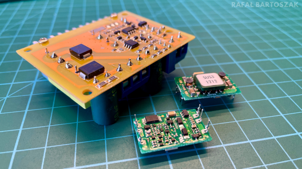
When discussing voltage converters, it is also worth knowing some characteristic parameters, typical of this type of design, these are:
- Input voltage range – this is the voltage range that determines what value the inverter can accept at the input and still work properly. This is important because different inverters have different input voltage ranges, and exceeding these limits can irreparably damage the entire design.
- Output voltage range – is the value of the voltage that the inverter is able to deliver at the output. Inverters can have a fixed output voltage or be regulated within a certain range.
- Maximum output current – determines the value of the current that the inverter is able to deliver
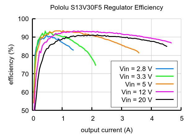
Quite an important aspect for inverters is their efficiency. This parameter determines how efficiently energy is converted. In other words, it is the ratio of power at the output to power at the input, often expressed as a percentage. Higher efficiency means less energy loss in processing and better performance. In the figure above you can see an example of inverter efficiency characteristics, the value, as you can see, depends on the input voltage and the current supplied by the system.
Classic blue inverter
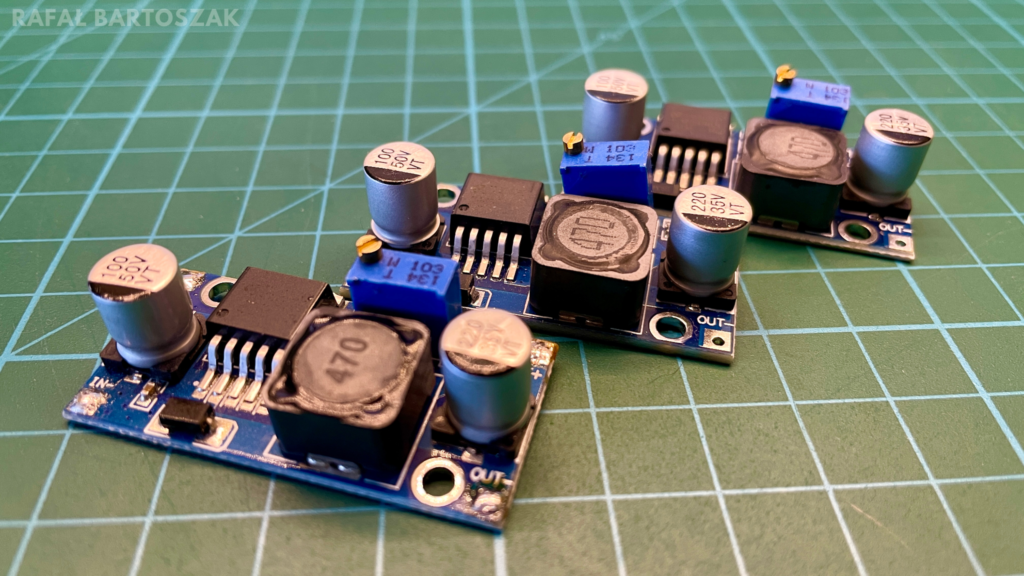
We already know the general principle of voltage converters, so we can take a closer look at one of the more popular “blue” designs based on the LM2596 chip. This simple voltage-reducing inverter, for its dimensions has quite a lot of possibilities. We can feed a maximum of 40V into its input, obtaining an output voltage from 1.2V to 35V at a maximum of 3A. The voltage is regulated by a potentiometer. This design, due to its price, is often used by many Sunday do-it-yourselfers.
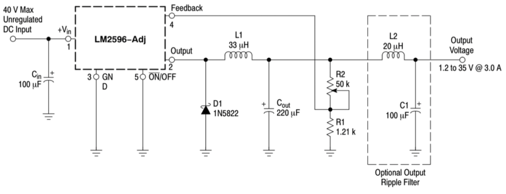
It must be said that the schematic is not too complicated and resembles the general concept of the inverter I showed you earlier. The whole thing is based on the LM2596 chip. A supply voltage is applied to the Vin input, which is filtered by an additional Cin capacitor. In addition to this, the chip also has, of course, a ground lead and an ON/OFF pin permanently connected to the negative pole of the power supply, thus forcing constant operation of this component. The Output output shows the voltage generated by the chip, which is based on the Feedback signal. It is derived from the output voltage processed by the resistor-potentiometer pair. By turning the potentiometer, we just modify its value, to which the LM2596 responds by changing the value of the output voltage. The elements of the inverter are also an inductor, a capacitor and a diode, whose task is identical to that in the previously described example. In addition, the schematic also includes an optional filter consisting of an inductor and a capacitor. Its task is to eliminate ripples, about which I will tell more later in the material.
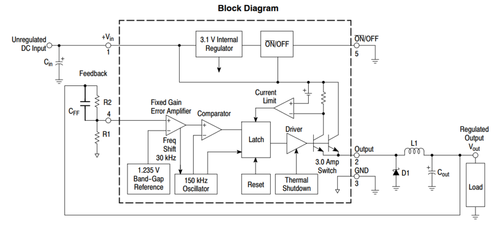
In the first example, the component that was constantly switched by the PWM signal was a transistor. Here, however, we have no transistor and no PWM signal. It was all encapsulated in a single IC, the aforementioned LM2596. This is a rather simple and already age-old design, but it is still in use nonetheless. As you can see in the block diagram above, all the components needed for the inverter are placed inside this chip.
The input voltage here goes to a pair of transistors controlled by a circuit consisting of a flip-flop and several operational amplifiers. Our earlier PWM signal here takes the form of an internal 150 kHz oscillator. Besides, a Feedback signal comparable to the internal reference voltage of 1.235V also takes an active part in controlling the transistors. It’s also worth noting that the last element controlling the transistors is the temperature protection, it should trigger when the circuit reaches 125°C, but from my practical tests it works pretty much as it pleases.
It must be admitted that this type of inverter is not at all a complicated device. In the rest of the article, all tests and descriptions will be based on just such an inverter.
Interference at the output of the inverter
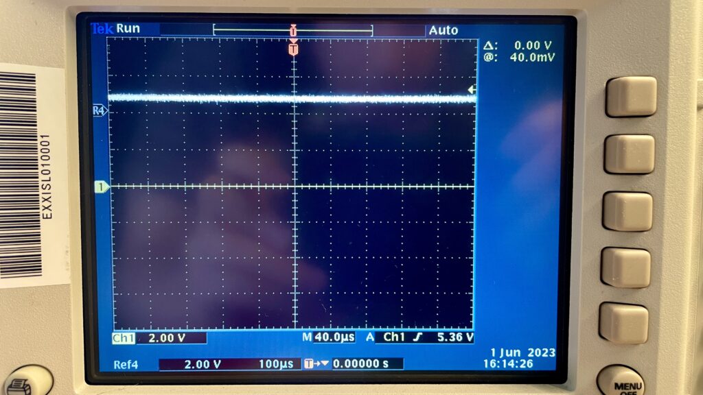
One of the problems that arise when using boost inverters is interference. We already know that this type of design is based on a constantly switching transistor, unfortunately, this state of affairs means that the generated output voltage will never be perfectly constant. There will always be smaller or larger disturbances, also known as noise or ripple.
In the photo above you can see the waveform from the output of the classic “blue” inverter presented earlier, with no load, in fact it only powers the LED soldered on the board. The design is powered by 12V, and I set the output to 5V. As you can see, the signal is quite stable, peak-to-peak voltage fluctuations reach a maximum of 100mV.
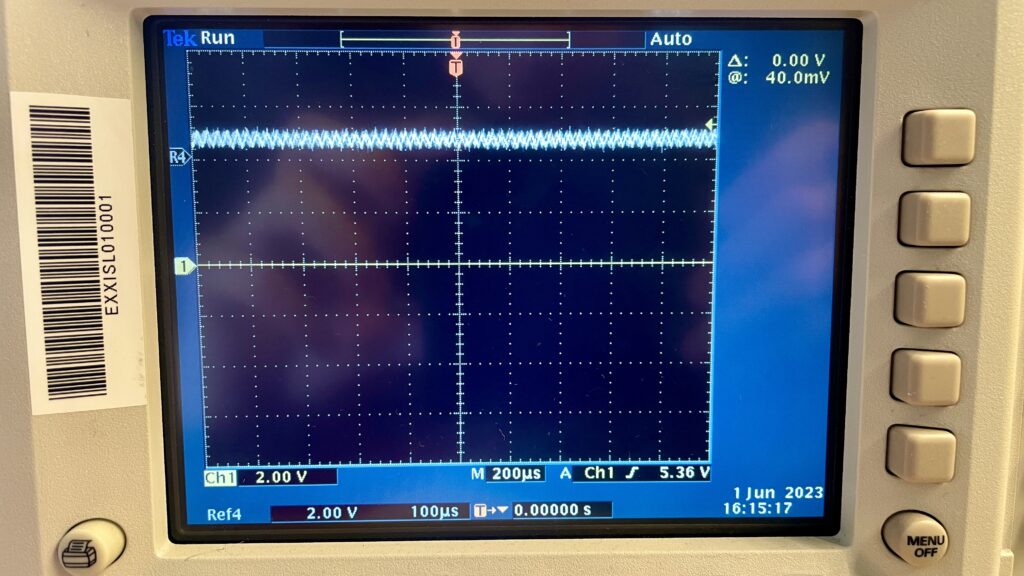
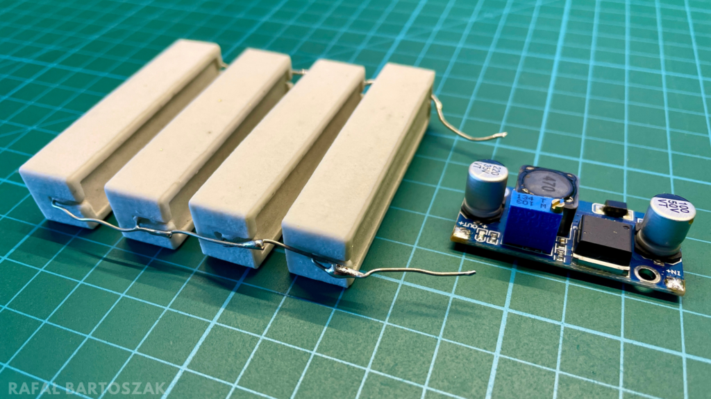
The situation changes when I connected several power resistors to the output of the inverter, which induces a current of about 1.4A. As you can see the waveform, has changed slightly, and already with the naked eye you can see small ripples. They reach a maximum peak to peak value of 800mV, also such a signal can hardly be called stable anymore.
The conclusion is that noise increases with the load on the system, and this is a feature of most voltage converters. Of course, depending on the design, they will vary in value, but they will always be undesirable. When building a power module, we want a stable voltage, regardless of the load. Without paying attention to the ripples, we can easily lead to malfunctioning of the powered circuit, or even in extreme cases to its damage.
In such a row, let’s consider whether the noise can be eliminated in some way. Of course it can, the easiest way would be to attach a capacitor in parallel to the output of the inverter to mitigate the ripple. A single capacitive element is really the minimum, a much better solution would be to add a properly selected LC filter, which, compared to the capacitor alone, would deal much better with high frequencies at the inverter outputs. Unwanted interference can also be the result of questionable quality components used by the module manufacturer. Here, too, I am referring to capacitive/inductive components; it may be worth experimenting by changing them to something of better quality.
The inverter is not working, why?
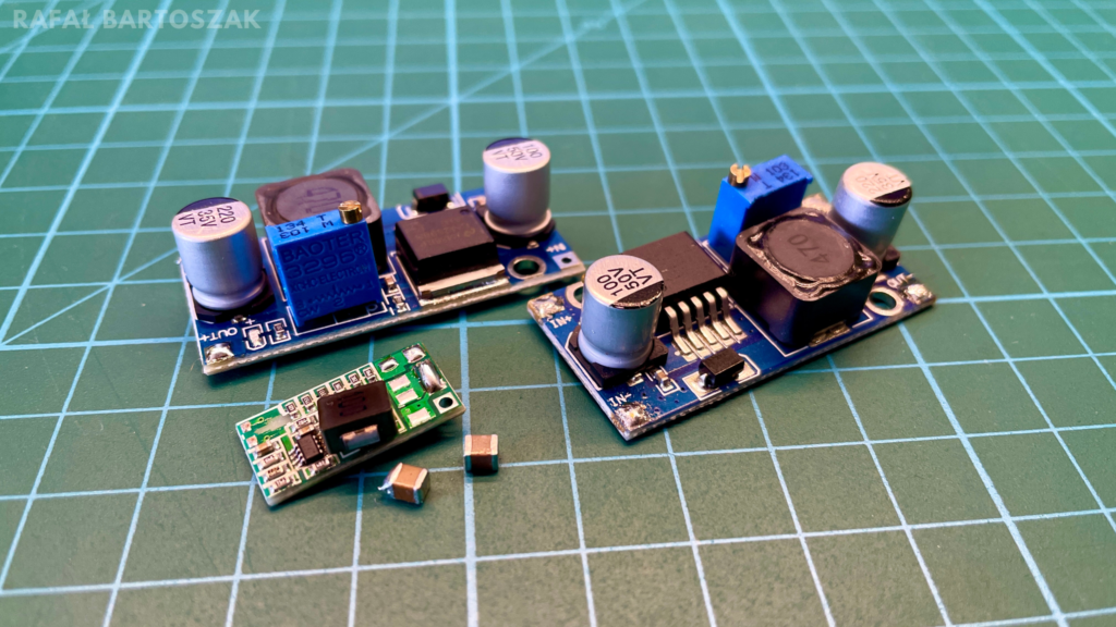
Initially in this part of the article I planned to include a description of typical faults associated with voltage converters, but in the course of collecting materials and practical tests it turned out that boost converters are quite robust designs. Despite the fact that at one point I quite deliberately connected the power supply in reverse, induced short circuits and overloads of 200% of power, the designs still work after all this time. The only interesting result of my tests, was that the components soldered off under the influence of flowing current.
You can see the mentioned effect in the video above. The output of this small inverter was shorted to ground, causing it to draw about 4A of current from my lab power supply. The first effects of the temperature caused by such current can be seen as early as the 6th second of the video, at which time the coil slides down slightly. Further on, you can see the tin working around the outer leads and ceramic capacitors, until finally one of the connections fails and the inverter goes down.
But let’s get back to the main thrust of this paragraph. Voltage converters are actually quite robust designs that damage quite often zero-one, stop generating voltage and that’s it. You usually have to look for the problem in the main IC, it’s the one that falls down most often. In addition, you also need to look for physical signs of damage. Deprived of the outer casing, the capacitor will quite clearly signal us that the power supply has been connected in reverse, in which case you can not do without replacing it. In fact, it is worth considering another issue – how to use voltage converters? This is quite an interesting topic, which most people do not even think about. In what follows, I will describe to you a certain issue, which I have laboriously called “the problem of the laboratory power supply”.
"The problem of the laboratory power supply".
Let him cast the first stone who has never done anything live. Every electronics technician knows that all circuit modifications should be done without power connected, but how the reality is, we all know very well. I myself must confess that this rule is not followed very often, resulting in a mass of damaged electronic components. However, it is nevertheless a good habit to disconnect the voltage, even if it is very low. I think that one of the reasons for frequent live operation is, in a way, laboratory power supplies, or rather their functionality. One could say that, after all, they have short-circuit and overload protection, even if something goes wrong, nothing will happen after all, but nevertheless, reality verifies this view more than once.
Laboratory power supplies have many different types of protection, but pulse voltage converters do not. The problem is that, more than once, we treat such simple modules a bit like the aforementioned professional designs. Already a complete absurdity are the designs available on the Internet for “home” laboratory power supplies based on just such voltage converters. The problem, which more than once causes the module to burn out, is its load, attached in the wrong way. With professional power supplies, we can afford to alternately attach and detach even quite current-consuming loads, but with DC/DC converters this can be deadly. These types of simple modules, are universal designs that are designed to work with a permanently connected load, which should otherwise draw a fairly constant value of current.
Imagine that to a running inverter we suddenly attach a high-power load, for example, an ordinary light bulb. The running inverter generates a certain voltage at the output, which at one moment is transferred to the tungsten filament. At the first moment, from the level of the inverter, the bulb looks almost like a short circuit, only after a while, when the filament has reached some temperature, its resistance increases. However, it is the first milliseconds that are important, the sudden load on the running inverter is quite a problem, because it must suddenly deliver a very large current. The most loaded element is, of course, the coil, or rather its core. In selecting this element, the designer of the universal inverter assumed some load capacity and saturation current, but the problem is that the coil may prove to be too weak. The core becomes saturated, the voltage drops, the current rises uncontrollably, one might say avalanchingly, and we have a ready-made disaster scenario.
How to avoid such damage? Do not attach a large load to a running inverter. A much better solution will be to start the load together with the inverter. Even simple and inexpensive modules support something like “soft-start,” a mechanism that will start the inverter in a controlled manner, adjusting its operation immediately to the attached load, even if it requires very large amounts of current at first.
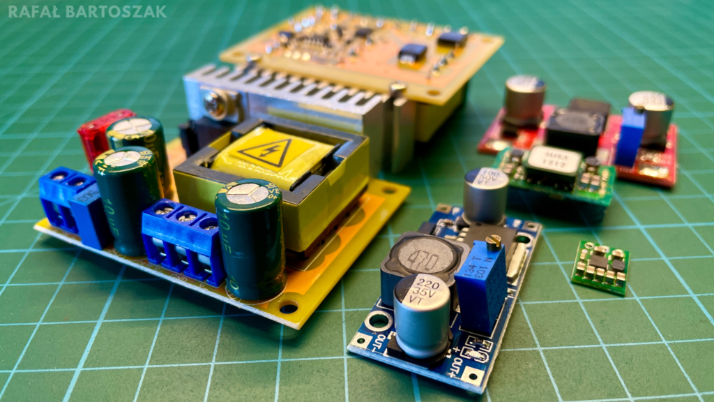
In a few words at the end, I can say that voltage converters are quite a complex topic, which I certainly have not exhausted. We have learned some basics, besides I have told you about some interesting problem of voltage converters, but there is still a mass of knowledge to learn. Perhaps in the future I will return to this topic, but for the moment I can only encourage you to play with electronics and not to be afraid of voltage inverters, as you know every problem can be an interesting lesson for the future.
On my site you will not find ordinary as well as automatically generated by Google Ads ads, in other words, I have no profit from running this site. But if you want to support my work, you can buy me a coffee. Thanks😊
Also see:
Sources:
- https://en.wikipedia.org/wiki/Voltage_converter
- https://en.wikipedia.org/wiki/DC-to-DC_converter
- https://botland.com.pl/blog/przetwornice-impulsowe-step-up-step-down-jak-to-dziala/
- https://elektronikab2b.pl/technika/54784-przetwornice-dc-dc-podstawowe-zasady-projektowania-rodzaje-kryteria-selekcji
- https://forbot.pl/blog/kurs-elektroniki-ii-przetwornice-impulsowe-id9923
- https://www.youtube.com/watch?v=6bicunweBAQ&ab_channel=GreatScott%21
- https://interelcom.com/baza-wiedzy/przetwornica-napiecia-czy-regulator-liniowy-ktore-rozwiazanie-wybrac/
- https://www.pololu.com/product/4082
- https://solderingmind.com/dc-dc-buck-converter-using-lm2596-ic/


