- Miniature clock with retro integrated circuit
Rumor has it that the only silicon structures that Polish engineers interfered with were clock circuits. It is difficult to confirm this, however, as it is known that factories in communist Poland produced silicon from ready-made designs, but not much is known about our native designs. At that time, technologies of this type were quite well protected, but who knows, there is a grain of truth in every rumor. Miniature clock with a retro integrated circuit
- MS1 – simple soft processor on FPGA
Everyone has thought about building their own processor at some point, well, maybe not everyone, but I happen to be in that small group of people. Almost from the very beginning of my interest in electronics, I was most fascinated by its digital aspects, and although programming was much more impressive, I enjoyed designing logic circuits the most. In the past, I built various designs that could be called simple processors or microcontrollers, depending on the solutions used. These devices were based on basic logic circuits, and although they were impressive at the time, over time their expansion became increasingly difficult and expensive, especially for someone who had just started high school. Wanting to learn more about the secrets of digital technology, I had to go a step further, and that's how I became interested in programmable circuits. This led to the creation of new designs based not on many separate chips, but on a single piece of silicon enclosed in an FPGA. However, I will talk about them, as well as the older, logical designs, in another article, because the subject of this text will be one of my most recent projects.
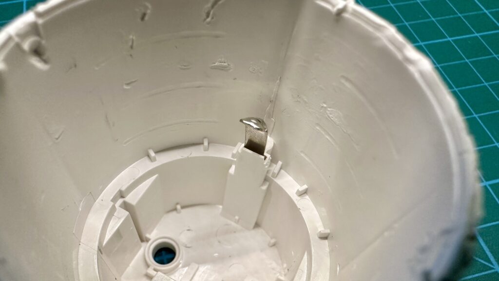
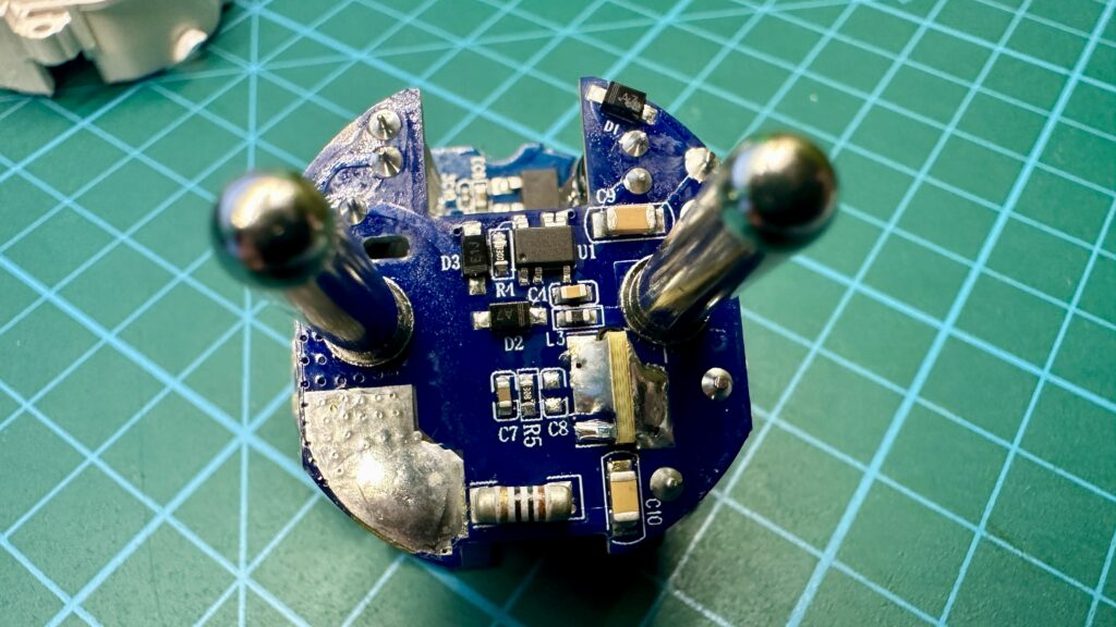
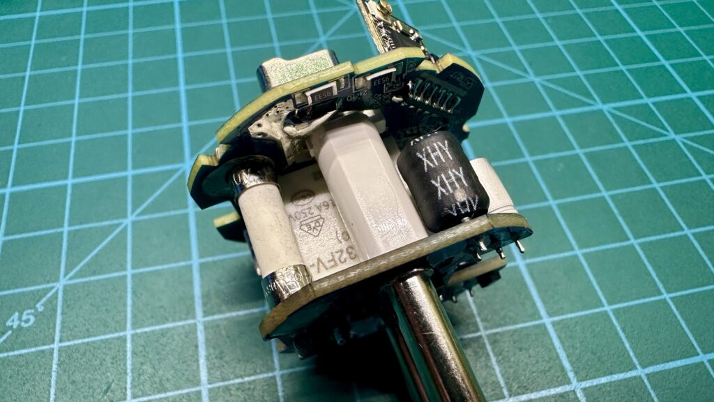
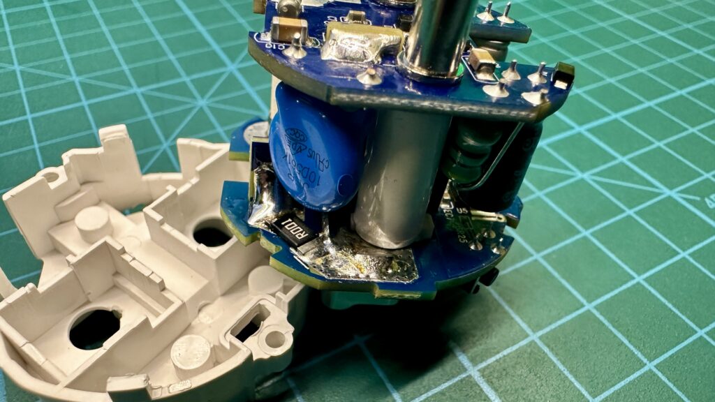
- Электроника 22-01 – Soviet travel clock
Today, few people remember such a thing as travel watches anymore, although those in the days before the spread of cell phones were readily used. One such device was the Soviet design Электроника 22-01 (Elektornika 22-10), which we will take a closer look at in this article.
- STM32 Ethernet – UDP Server
Recently I had the opportunity to work on some project using STM32 microcontroller and Ethernet interface. Probably like other people undertaking this topic, I encountered a problem - the lack of “simple” tutorials. In most of the available sources, connecting the Ethernet interface and STM32 chips is described quite confusingly, and in my opinion, there is a lack of instructions describing how to configure this functionality in the simplest possible way, without unnecessary exploration of network aspects. That's why I decided to prepare this and related material covering the topic of Ethernet on STM32. In this article I will show you the basic functionality of the UDP server.
- Intel’s forgotten registry
What was the name of the first personal computer? The answer to this question depends on the answerer. According to the Computer History Museum located in Silicon Valley, it was the Kenbak-1.