When taking DC voltage measurements with a multimeter, we usually don’t think about its accuracy. Receiving a result of 5.1V, when we expect something in the neighborhood of 5V, we assume that the multimeter’s indication is correct, telling ourselves that simply at the output of the power supply or the USB port of the computer the potential difference is slightly higher than expected. However, are we sure? After all, we can’t so straightforwardly exclude the situation in which it is the measuring apparatus that generates results that are inconsistent with reality. In this case, is there any way to determine the “true” voltage at the said USB port? Unfortunately, the answer is no, we are always condemned to a certain accuracy and the measurements made are always subject to some error. Smaller or larger, in a charming way, we can say that it depends on the class of measuring equipment, but it should be remembered, however, that the accuracy of measurements of electrical quantities is a really extensive topic, which has already been covered in many books and articles.
Some time ago on the YouTube channel of Mr. Piotr Górecki, whose work I highly recommend, as well as the magazine Understanding Electronics, there was a video addressing the topic of integrated voltage patterns. In the material, Mr. Piotr tests, among other things, the now century-old MAB01 chips made in Czechoslovakia, which I associated with me that I had already seen somewhere. Searching through my “electronic junk”, I even managed to find two such chips, which I once bought as typical stock loungers. Inspired by the video and Mr. Peter’s article, I decided to perform a similar test of these, as well as several other voltage standards, also adding Zener diodes, IC stabilizers and DC/DC converters to the set.
With this, I would like to add my three cents to the topic of integrated voltage standards. In addition to the tests, I will tell you a bit about why Zenar diodes, seen by many as voltage standards, cannot be treated that way, and why stabilizers and inverters are completely unsuitable for generating reference voltages, an opinion I also once encountered, which is downright aberration. At the very end, we will also take a look inside the Czechoslovakian MAB01 circuit, but let’s start from the beginning.
What is a reference voltage source?

Obtaining a stable voltage source is not all that simple, as I mentioned earlier, every measurement is subject to some error. The class of measuring apparatus, its accuracy, temperature variations and resistance of measuring wires are just a few examples of factors that can adversely affect electrical voltage measurements. In addition, we must remember something like the voltage standard used, for example, in a multimeter. Each measuring equipment in its interior must have a certain reference module on the basis of which the value of the measured parameters is determined. These can be implemented in different ways, in the simplest form the source of the reference voltage can be a Zener diode, but a much better element here will be an integrated standard, on the basis of which larger modules are often built, generating the most stable reference voltage.
Regardless of how the reference voltage module will be realized, its task always remains the same. To generate a bordering on ideal voltage, the value of which will always be the same, regardless of the conditions under which the measuring apparatus will work. It can be said that the more accurate the reference we have, the more accurate the meter’s indication will be.
It should also be mentioned that reference voltage sources can also be found in other devices. It is used for various types of comparators and D/A and A/C conversion modules. The more accurate the voltage reference is, the more accurately we can determine the value read from, for example, an analog temperature sensor. Besides, voltage standards are also used in regulated power supplies. Thanks to them, the device can provide the most accurate and stable voltage, compared in real time with the standard value.
Are my electrical voltage patterns working?
Looking through my electronic resources, I finally managed to find four circuits that are voltage patterns. The first two are typical stock lagers dating back to the days of the defunct Czechoslovakia, also their age I estimate at 40/50 years. They are designated MAB01D, and interestingly these chips are a socialist copy of the third chip, the REF01C. This one, too, is a stock lager manufactured by Analog Devices, the age of which, unfortunately, I am unable to determine. The last chip is the LT1021, which was manufactured by Linear Technology. This chip must have been pulled from somewhere, as solder marks are visible on its leads.
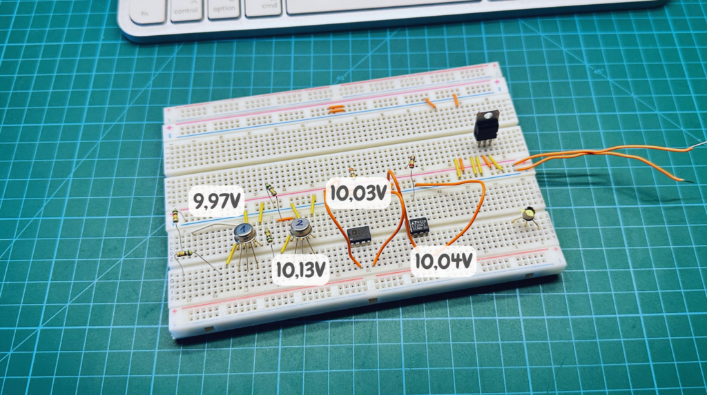
Each of these circuits is a reference that, according to the documentation, generates a voltage of 10V. In their basic configuration, all you need to do is supply energy to the circuit, and there will be, in theory, an ideal reference voltage at its output. And that’s the test I decided to perform first, to essentially see if these circuits work at all. It is also worth mentioning that voltage patterns can also be run in much more elaborate circuits with feedback, but in my tests I will use only the basic application.
After connecting the voltage at the output of each chip, a voltage around 10V appeared, also proud to say that the chips are probably working properly and it will be possible to perform (un)professional tests on them. From the voltage readings, it appears that the first chip MAB01D and REF01C are closest to the expected 10V. The LT1021 deviates slightly from them, while the second of the Czechoslovakian designs performs worst. However, this test is by no means authoritative. The chips were supplied with 15V, operated at room temperature, and I took measurements with an ordinary Stanley STH77364 multimeter. I must emphasize here that this was only a test run to see if, at first glance, my voltage patterns work. I will conduct more concrete tests later.
(Un)professional tests
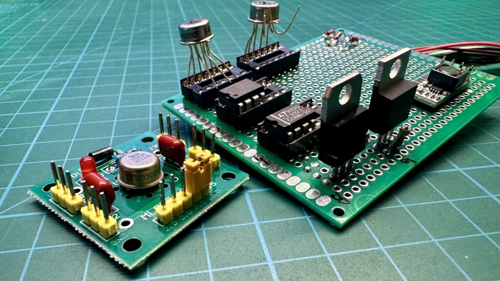
For the next test, I decided to prepare a slightly larger board, on which he also accumulated slightly more components. To the ranks of the above-mentioned voltage standards joined one more construction – a Chinese standard module with the AD584JH chip. This is a budget design, which can be purchased for as little as a few dozen zlotys. The module is in the form of a small square board, which also included capacitors, a resistor and two rectifier and light-emitting diodes, the connection to this design is made via goldpins, but in my tests I soldered directly to the circuit leads.
Besides, I also placed three identical Zener diodes of 0.5W and 5.1V on the prepared board. Each of them is accompanied by an individual 1.2kΩ resistor that limits the current flowing through it. Thus, the diodes were run in a basic configuration so that it is possible to obtain the Zener voltage, which in many designs can be found as a reference voltage. It is also worth mentioning that the resistors used are completely “ordinary” cheapest resistors and are not precision designs, this will be important in later applications.
In addition, the board features an L7810CV stabilizer and a rather popular small DC/DC converter that lowers the voltage. On its bottom there are several jumpers, which are responsible for selecting the voltage that will appear at the output of this design. With the help of tin, I connected the two pads, at which there was a 5V marking. In the confrontation, which I will describe later, we will check how these components perform both with and without a load. Their role will be played by power resistors selected so that the current flowing through them is about 500mA. We can’t consider stabilizers and inverters as voltage standards, an opinion I once encountered, because, after all, “voltage is voltage.” Therefore, I will try to prove that this is a big mistake. On the board you can also notice an adjustable LM317 stabilizer, but this one fell out of the whole comparison, mainly by the fact that it is adjustable.
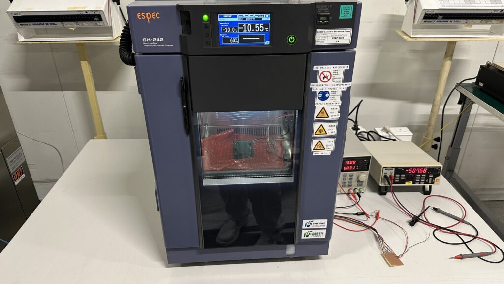
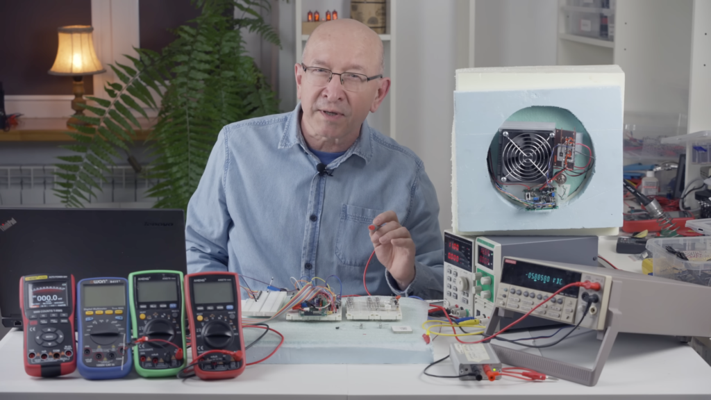
Test stand.
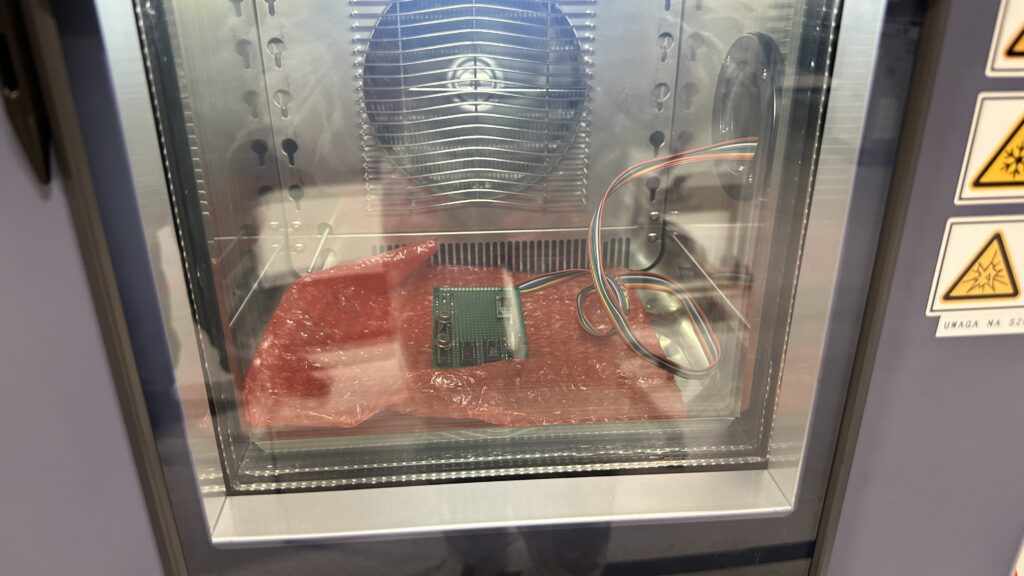
The premise of the test I made was to see how the collected electronic components would behave at different temperatures. The test wafers were placed inside the climate chamber, and the attached wire was brought outside. This allowed for non-invasive power supply and voltage reading from the individual standards. The potential difference was read from -10°C to 30°C, in two-degree increments. Besides, at the end, the test samples were heated up successively to 40°C, 50°C and 60°C, and the voltage was also read at these values. The humidity inside the chamber was set at 60%, and it actually oscillated around this value.
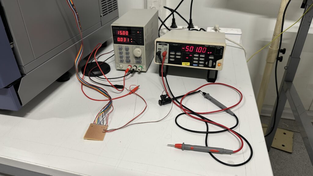
The sample was supplied with 15V from a Korad KA3005D laboratory power supply. Meanwhile, the measuring apparatus is a 5.5-digit Hioki 3237 laboratory multimeter, whose voltage measurement accuracy is +/-0.025%.
If the measurement results or graphs are barely visible, open them in a new tab.

I put the results of the measurements in a summary table, which you can see above. Based on it, I generated several charts using Excel, which will serve as material for more detailed analysis in the following section, although specific measurements are also worth noting.
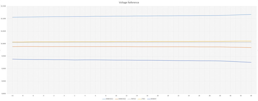
Looking at the graphs, it is much easier to see the difference between the components. In the category of voltage patterns, REF01C and LT1021 are the best performers. This may come as a bit of a surprise, especially since the chips are already years old. However, as you can see, the voltage they generate oscillates very close to the 10V value, with differences appearing only at the third decimal place.
Slightly worse, but still decent performs the second of the Czechoslovakian designs. The voltage value here is only two hundredths short of the desired value.
Another is the AD584JH, which surprised me a bit. I thought it would do much better, and it lost out to three already aged designs, and it’s hard for me to judge why. The voltage generated by this chip is roughly seven hundredths short of the benchmark value of 10V.
The worst performer was the MAB01D, marked with the number one. The voltage on this standard is more than a tenth more than 10V, making the design not really suitable for an accurate voltage standard. Therefore, we will return to it later in the material.
As you can see, each chip also responds to extreme testing at 30°C, 40°C, 50°C and 60°C. The voltage generated then slightly increases or decreases depending on the specific chip.
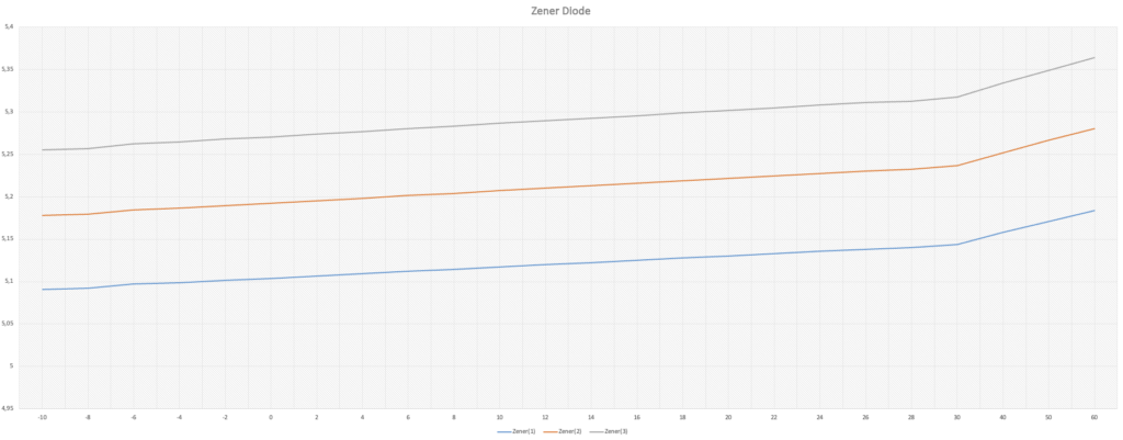
The desired voltage for Zener diodes was 5.1V, and as you can see, none of the designs hold this value. In fact, only on the first diode does this voltage appear around 0°C. As the temperature increases, the voltage increases at a fairly similar rate in each case, but the magnitude of the discrepancy between the readout value and the desired value is so large that one can say without a doubt that treating Zener diodes as voltage standards is not the best idea.
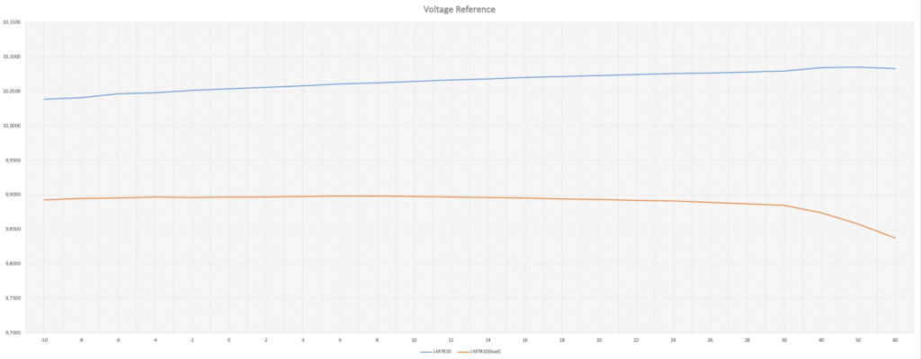
The next component tested was the LM7810 integrated stabilizer. As you can see, it did not reach the declared value of 10V, which without a load was about five hundredths higher, while with a load it was more than one tenth lower. You will note that the stabilizer line with the load connected is slightly more stable in most of the temperature range. Only at higher values does the voltage begin to drop much more.
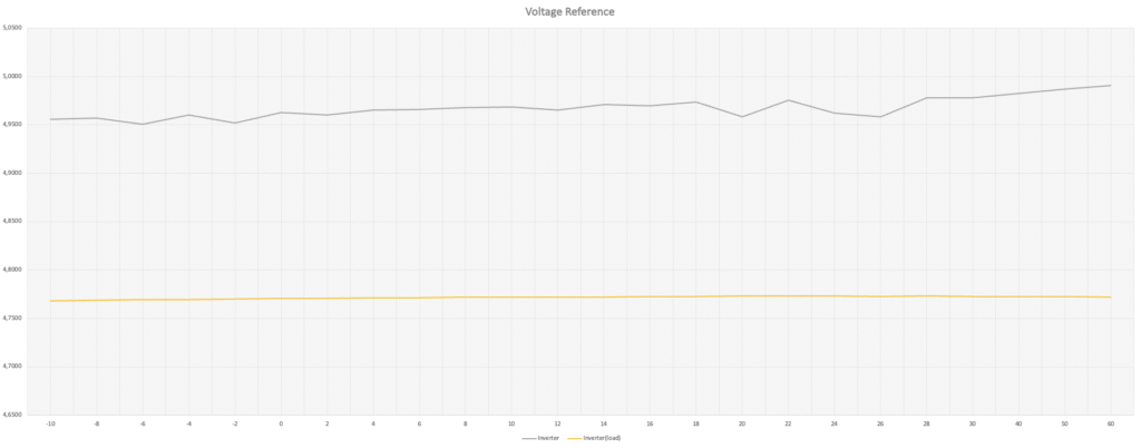
The last component to be checked is the miniature inverter module. Like the stabilizer, it did not reach the desired voltage of 5V, with values from the load more than two tenths lower. Without a load, the potential value is close to the desired value, but we can notice some fluctuations. These are due to the pulsed nature of this component, which I mentioned a little more in an earlier article – What do you need to know about voltage converters?
What will be the best electric voltage standard?
The answer to the question of what would be the best voltage standard, based on the results of my measurements, is quite obvious – a voltage standard. These elements are dedicated to generating the most accurate value possible regardless of temperature, humidity or even the parameters present in an electrical circuit. Zener diodes, although considered by many as reference elements, should be treated with some distance. Zener voltage variability can be quite large, so we can only use these elements in less demanding applications where long-term stability is also less important.
Switch-mode inverters and stabilizers can be, sources of supply voltage, but in no way should they be a reference. Their variability and susceptibility to external conditions is even enormous. Besides, noise and ripple can appear in power supply circuits, which have a messy effect on the stability of the generated voltage.
At the end of this section, I must mention that I called the previous subsection unprofessional tests for a reason, as it is just a general look at the topic of voltage patterns. I deliberately omitted a more thorough control of the humidity in the chamber, the value of which was surprisingly stable anyway. Metrological aspects, such as the class of equipment used, its preparation or the resistance of the wires, also received little attention, since my goal was only a cursory examination of the subject, although the readings nevertheless allowed me to draw conclusions consistent with the literature.
What is hidden inside the socialist structure?
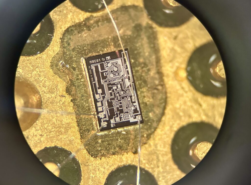
As I mentioned earlier, it’s time to return to one of the Czechoslovakian designs. Since the MAB01D chip with index one fared the worst in the confrontation of voltage patterns, I decided to take a look inside to get a little closer look at the structure of the silicon core. You can see a collection of microscope images below.
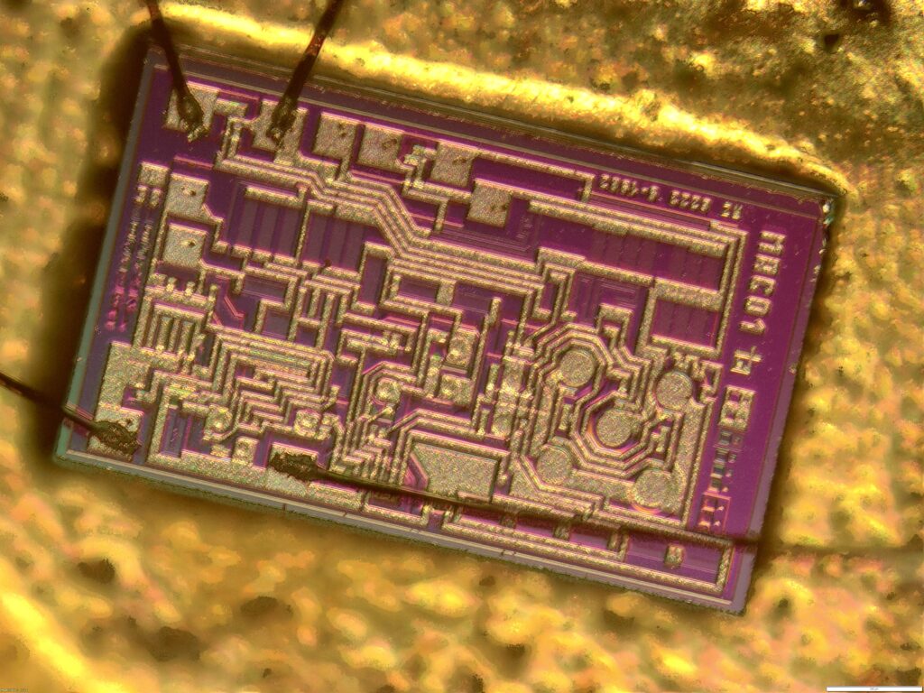
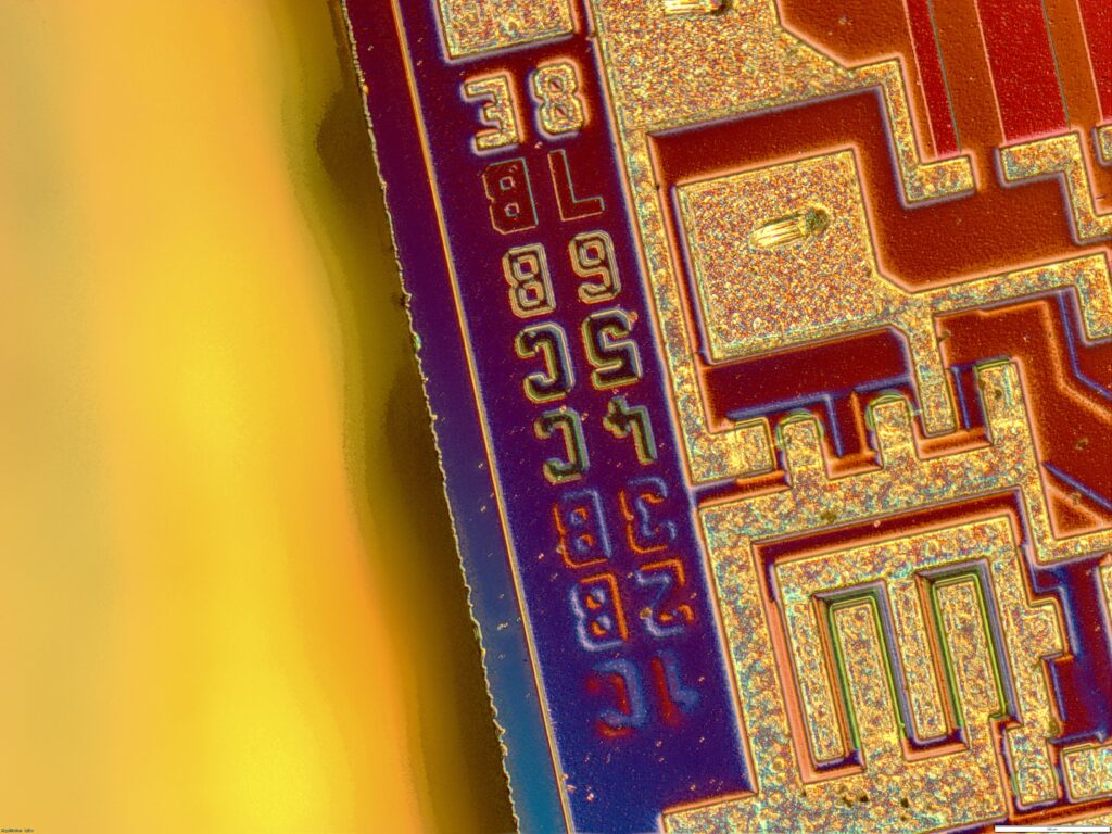
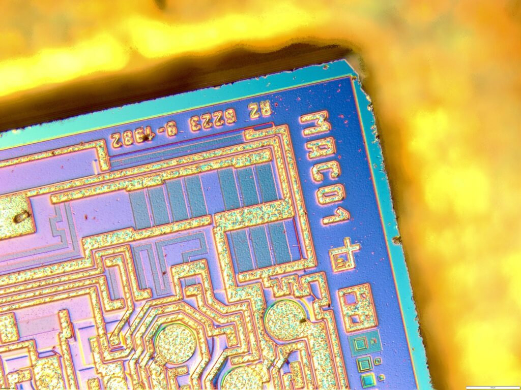
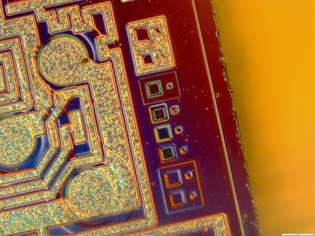
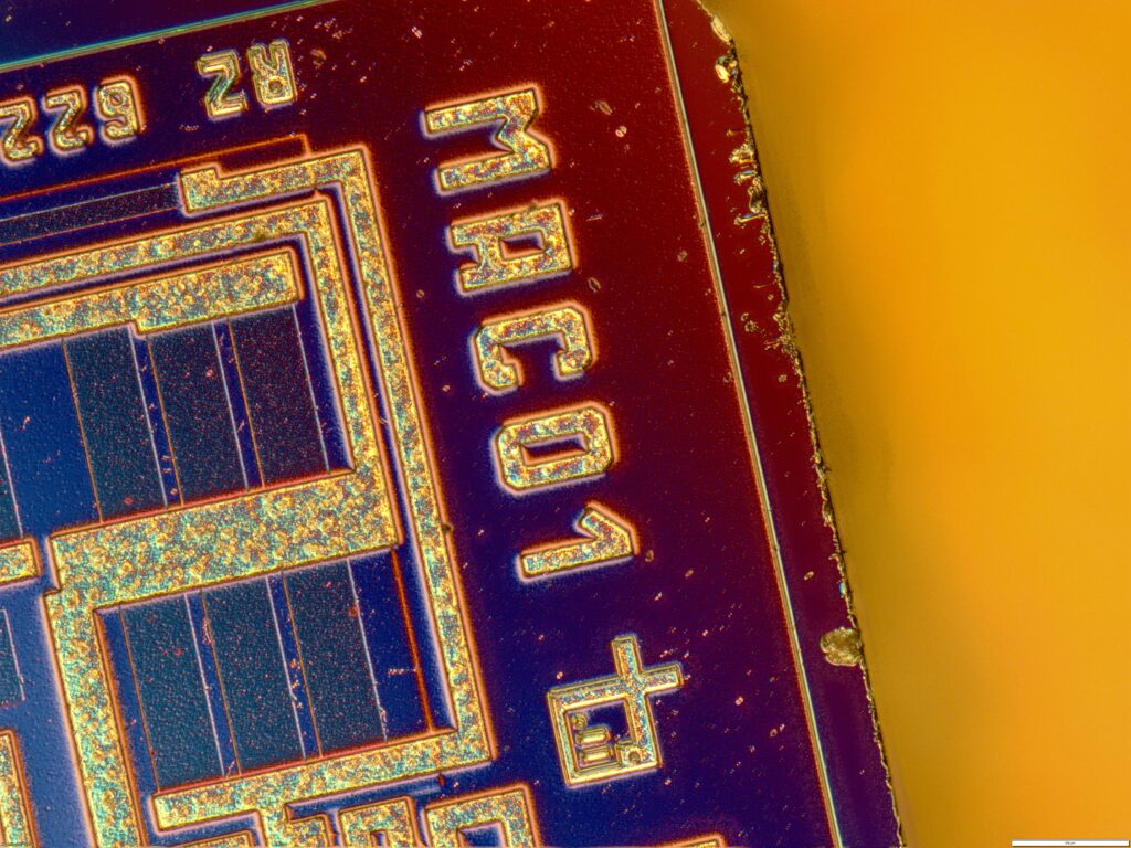
Microscopic photographs of the MAB01D chip.
Looking inside the MAB01D, we can notice a few details. As I have already mentioned, this chip is in fact a copy of the Western REF01C, stripped, among other things, of the temperature feedback circuit. There are chert leads connected to the silicon substrate, but fields for more gold wires are also visible. This may suggest that, in terms of silicon, this design is not necessarily a truncated version of a Western circuit. It is likely that the circuit is complete, but for some reason the engineers at the Czechoslovakian factory decided not to use them.
In addition, we can see the MAC01 marking on the core, as well as quite a few markers and patterns, which may have been useful during quality control. On the surface, we can also notice small contaminants, which were formed during the opening of the chip case. Besides, attention is drawn to the frayed edges of the core, which are most likely original.


Sources:
- https://www.youtube.com/watch?v=bfcqgDcBork&t=170s
- https://piotr-gorecki.pl
- https://en.wikipedia.org/wiki/Voltage_reference
- https://uk.rs-online.com/web/content/discovery/ideas-and-advice/voltage-references-guide
- https://www.nutsvolts.com/magazine/article/build_a_01_accurate_voltage_reference